2023-12-13
14
Edit Mesh (Extrude)
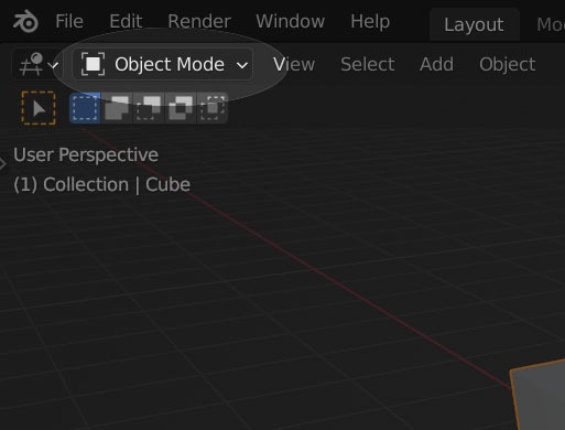
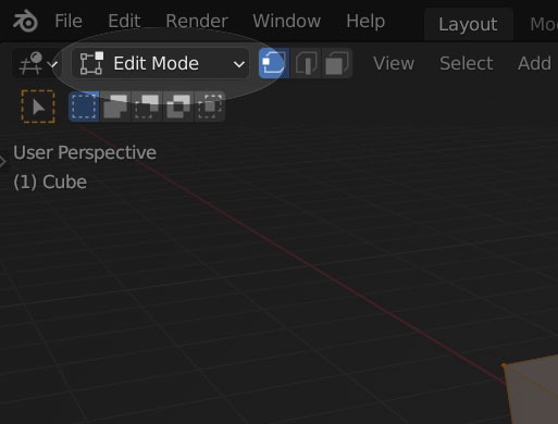
Tab (Object Mode / Edit Mode)
Let’s move on to Mesh editing.
From now until the end of the first session, let’s master Mesh editing in one go.
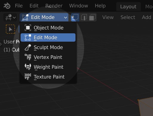
You already know how to switch to Edit Mode by pressing
Pressing the
Edit Mesh (Extrude)
Once you’re in Edit Mode with the
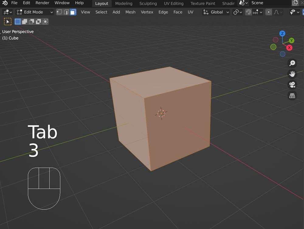
After selecting a face with
This immediately enters the Extrude mode, allowing you to extrude the face along the mouse movement.

The above image shows a selected face.
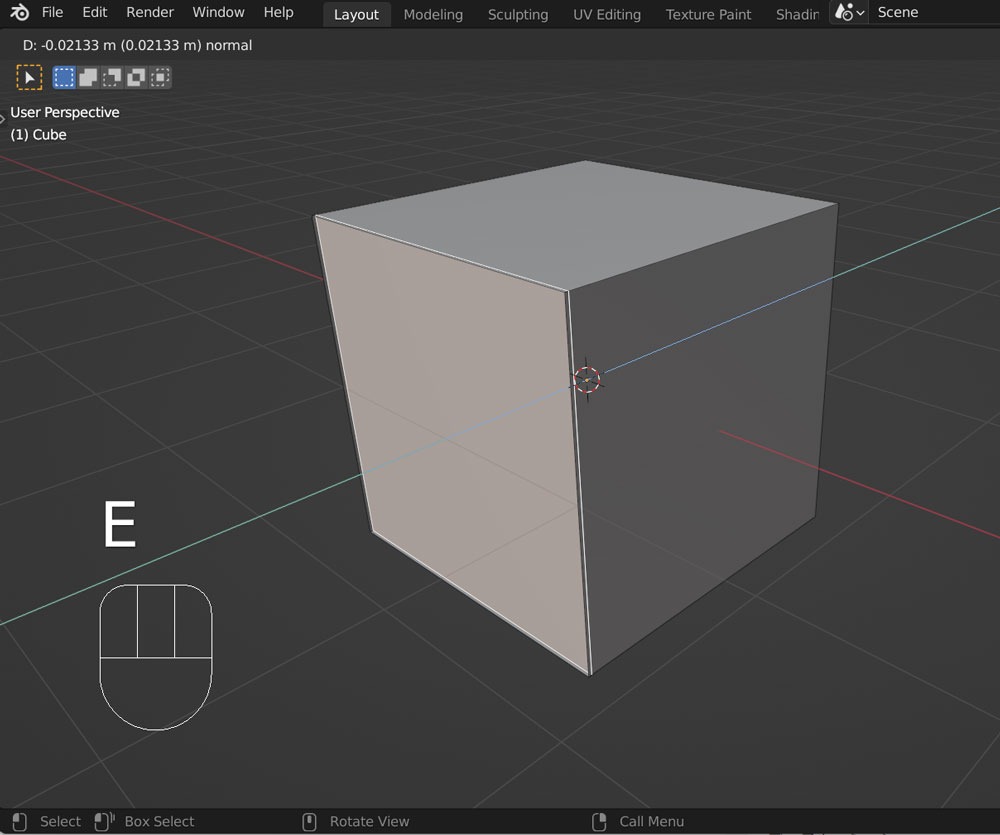
The above image is right after pressing
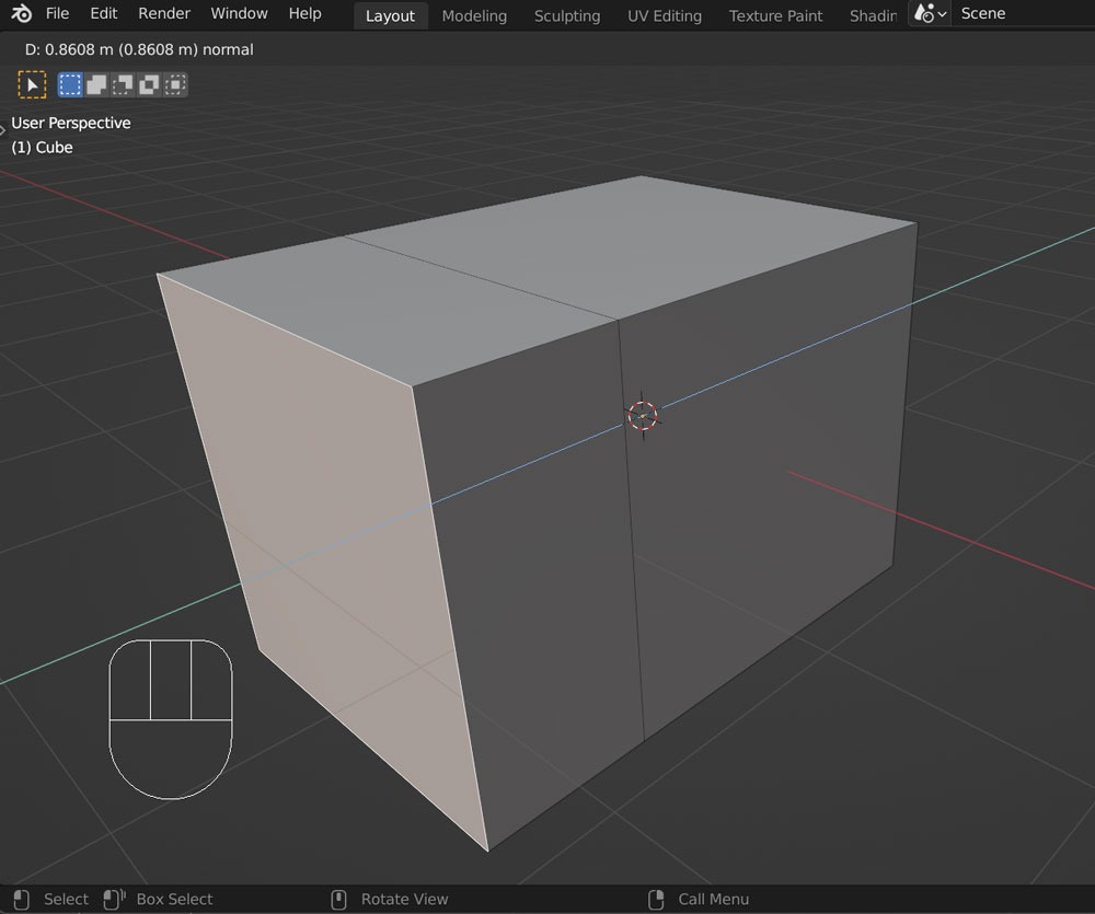
Then, when you move the mouse, the face is extruded, and the side becomes visible.
Finally,
In the case of Extrude, unless specified otherwise, it is extruded in the normal direction.
The normal is the “orientation of the face.” In the face’s coordinates, the normal is the Z-axis.
Therefore, the face is extruded in the direction of the normal, and you see the blue guide lines indicating the normal direction.
Like
For example,
extrudes in the normal direction by a distance of 1.
Moreover,
For example, you can select a vertex and start shaping freely from there.
Here is a video summarizing the above operations.